Tutorials › 4
Leads, dogbones and T-bones
A round bit can't cut a square inside corner, and plunging on the finished edge leaves a mark. This tutorial cuts a finger-jointed box side that fixes both.
-
Draw or import the part
Import the outline as a DXF, SVG or PDF with ⌘I, or draw it. Here the part outline has fingers along both ends, and a 3 × ¾ inch rectangle makes the handle slot. Set the material to ½ inch plywood under Material & Machine.
-
Add two profiles
Select the handle slot and add a Profile toolpath with Side: Inside. Select the outline and add another with Side: Outside and tabs. Keep the slot's toolpath above the outline's in the sidebar, so the part is still held while the slot is cut. (Toolpaths ▸ Optimize Run Order always keeps the work inside a part before its cut-out.)
-
Turn on leads
In each profile's Leads section choose Arc. The bit now comes onto the cut along a tangent arc in the waste and leaves the same way, so it never plunges or stops against the finished edge. With a ramp entry, the ramp runs down the lead and on along the wall.
- Radius and Sweep size the arc; Line comes in straight at an angle instead.
- Lead out leaves the loop on a lead too, and Overlap runs the last lap a little past its start to hide the seam.
- Leads stay on the waste side, on the material and clear of clamps, and shrink (down to a quarter of the bit's radius) to fit small holes. A loop with no room is entered without one, and Checks says how many.
-
Relieve the inside corners
In the outside profile's Corners section choose Dogbone. Each inside corner of the fingers gets a short cut along its bisector until the bit's edge touches the drawn corner, about 0.29 × the bit's radius past each wall on a square corner, so the mating fingers seat fully.
For the handle slot choose T-bone. A T-bone cuts past the corner along one wall, so the notch is only in the other. T-bone side puts it in the longer side by default. T-bones suit slots about as wide as the bit, where dogbones would overlap, and they're easier to hide.
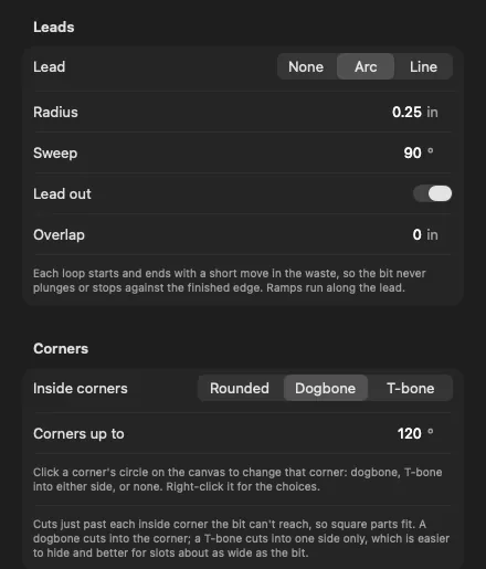
Leads and Corners in the outside profile's inspector. Corners up to is the widest corner that's relieved, measured across the cut-away area: 90° is a square corner, and the default, 120°, includes hexagons. Flatter corners and faceted curves are left alone.
-
Check it on the canvas
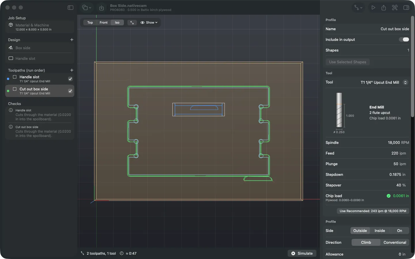
With a profile selected, each relieved corner is circled on the canvas at the bit's position at the end of the relief. Press ⌘1 for a top view.
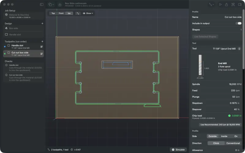
Dogbone circles at the fingers, the T-boned slot, and the arc lead-in at the bottom. Corner by corner: click a circle to step that corner through dogbone, T-bone into one side, T-bone into the other, and no relief. Right-click it to pick one, or choose Use Toolpath Setting to go back. Changed corners are drawn in the accent colour, and a relief that would cut into nearby geometry gets an orange cross. Corners ▸ Reset clears them all.
-
Simulate
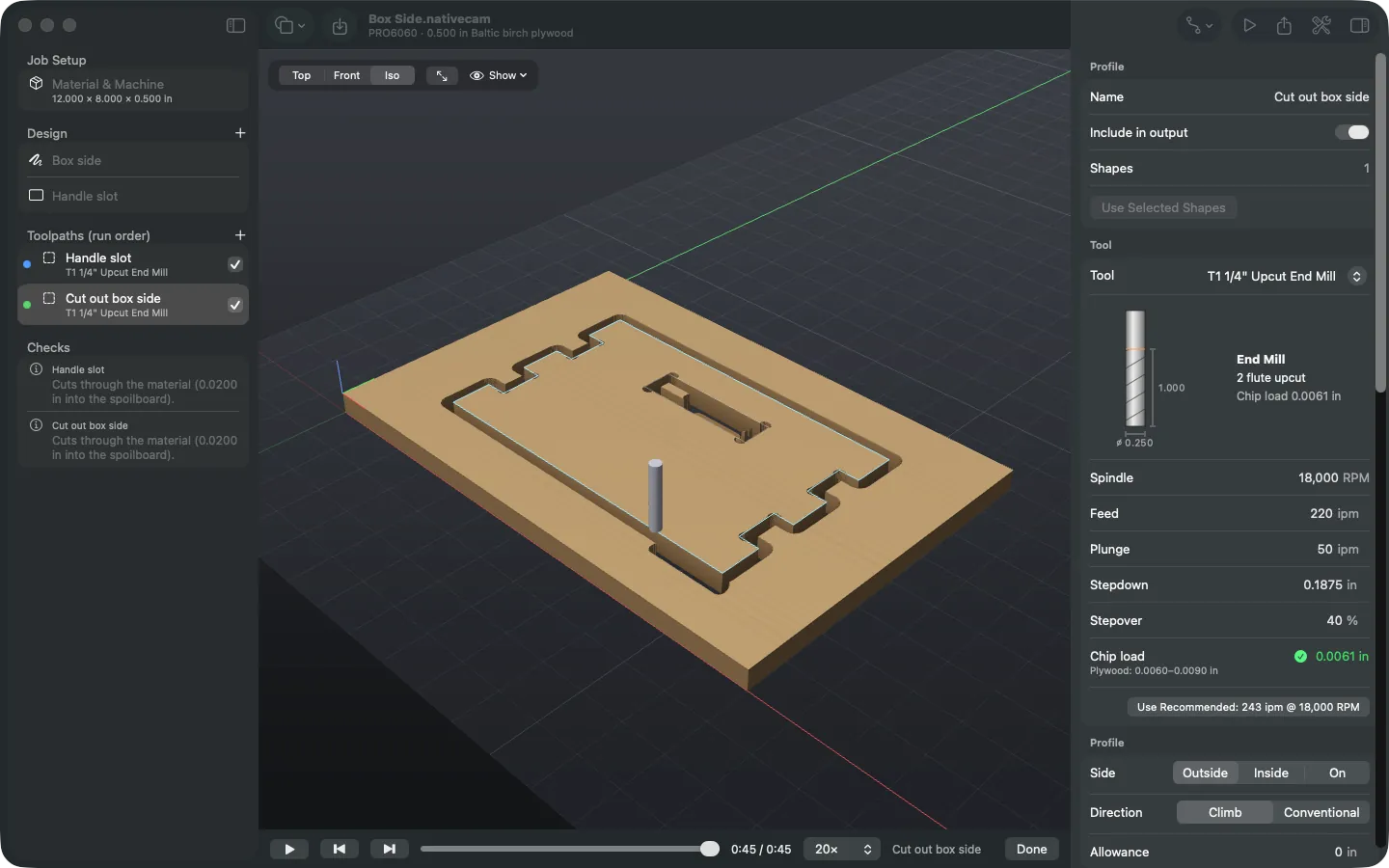
Press ⌘R and look at each corner and where each loop starts and ends.
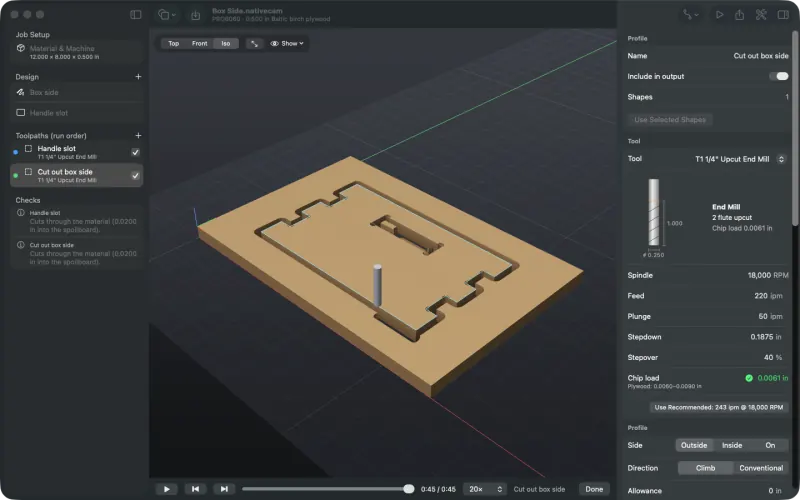
The finished part in the simulator.
Things to know. Leads only keep clear of the shapes in their own toolpath, so put parts that sit close together in one profile, or use a smaller lead. A corner's own relief choice is tied to its place on the shape: resize the shape so that corner moves and the choice no longer applies (Checks says so). Very sharp corners get long reliefs, so check the preview. See known limits.